In IP Telephony World, RSVP is a CAC
mechanism that can reserve bandwidth for the length of the call. If any router
along the path cannot reserve the requested bandwidth, the originating gateway,
CUBE, or CallManager can reroute the call, send it with different marking, or
drop it.
One drawback to RSVP is that the
reservation process causes some delay in call setup. To minimize this, include
RSVP control messages LLQ.
RSVP Signaling
Its Network control
protocol (protocol number 0x2e and operates at L3) that allows internet
applications to reserve QoS resources for their traffic. Note that RSVP will do the
signaling for reservation but the actual reservation should be done by queuing
mechanisms.
RSVP messages
1. Path Message
It’s
sent by the sender through the path provided by routing protocol towards the
receiver. It will store flow info in each node and enables each node to realize
the previous and next hop of the session. Those messages are sent periodically.
They are used to form RSVP neighbor ship.
2. Reservation Message
Those
are sent from receiver to sender and should follow the exact path of Path Message (it will use Path messages to
obtain reservation message path). It’s used to maintain reservation state in
each router. It is sent periodically.
3. Confirmation and Error
Messages
Those
are classified as path-error, reservation-error, and reservation-acknowledge
messages. Path error messages are generated from path messages and in direction
towards sender. At each hop the destination address is the previous hop.
Reservation error messages are generated by reservation request and sent
towards the receiver. Information carried in error messages can be:
- Admission failure
- Bandwidth not available
- Service not supported
Reservation
acknowledgments are generated by sender to confirm the receipt of reservation
request.
4. Teardown Message
Those are used to remove RSVP state from each node
without waiting for timeout. It can be initiated by host to tear down
reservation or router in case reservation timed out. It has two types depending
on the initiator (sender/receiver): Path teardown and reservation-request
teardown.
RSVP operation
A
typical RSVP session involves the following sequence of events:
- A potential sender starts
sending RSVP Path messages to the session address (destination address).
- The receiver receives the
Path messages.
- The receiver sends
appropriate Resv messages toward the sender through the same path of Path
messages. These messages will carry FlowSpec, which is used by routers
along the path to make reservations in their link-layer media.
- The
sender receives the Resv message, and then it starts sending application
data.
Once those steps are
completed successfully, RSVP demon will set arguments in packet classifier (to
identify RSVP flows) and packet scheduler (on routers) for the desired flow to
be processed using the underlying queuing mechanism.
Note that this
sequence of events is not necessarily strictly synchronized. For example,
application data can flow before the sender receives Resv messages. Application
data that is delivered before the actual reservation contained in the Resv
message is typically treated as best effort, nonreal-time traffic with no QoS
guarantee.
RSVP reservation Style
Before
proceeding with reservation style, four terms should be defined:
- Distinct reservation: Each
receiver establishes its own reservation with each upstream sender.
- Shared reservation: All
receivers make a single reservation that is shared among many senders.
- Explicit sender: List all
selected senders.
- Wildcard
sender: Select all senders, which then participate in the session.
Reservation
style is used by the receiver to define how reservations are accomplished with
multiple senders. From the above options, below reservation styles were
defined:
- Fixed filter (FF): This
reservation style consists of distinct reservations among explicit
senders. Examples of applications that use fixed-filter style reservations
are video applications and unicast applications, which both require flows
that have a separate reservation for each sender.
- Wildcard filter (WF): This
reservation style consists of shared reservations among wildcard senders.
This type of reservation reserves bandwidth for any and all senders, and
propagates upstream toward all senders, automatically extending to new
senders as they appear. A sample application for wildcard filter
reservations is an audio application in which each sender transmits a
distinct data stream. Typically, only a few senders are transmitting at
any one time. Such a flow does not require a separate reservation for each
sender; a single reservation is sufficient.
- Shared
explicit (SE): This reservation style consists of shared reservations
among explicit senders. This type of reservation reserves bandwidth for a
limited group of senders. A sample application is an audio application
similar to that described for wildcard filter reservations.
RSVP Basic Configuration
RTR(config-if)#
ip rsvp bandwidth
!! Enable RSVP on interface. Without this
RSVP messages can’t be received/send. Also, once reservation installed, BW will
be subtracted from max-reserved-bandwidth.
RTR(config)#
ip rsvp sender session-ip-address source-ip-address protocol
des-port-num src-port-num previous-hop-address previous-hop-interface bandwidth
burst-size !! Install RSVP sender statically in DB.
ip rsvp sender-host command can be used to simulate sender (use proxy feature).
Same can be done for receiver.
RTR(config)#
ip rsvp neighbor access-list
!! To restrict RSVP
neighbors
RTR(config)#
ip rsvp udp-multicasts des-address
!! Instruct the router to
send UDP multicasts whenever it generates IP multicasts. This is required
sometimes for trigger other hosts.
RTR(config-if)#
ip rsvp precedence conform value
exceed value !! Set IPP
RTR(config-if)#
ip rsvp tos conform value
exceed value
!! Set ToS
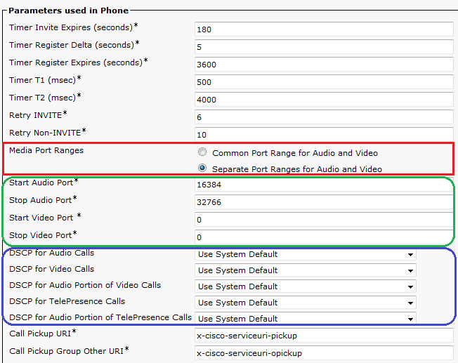
RTR(config-if)#
ip rsvp signaling DSCP value
!! Set DSCP value for RSVP
messages to prioritize them
SENDER-1#sh ip
rsvp interface detail fa0/1
Fa0/1:
Interface State: Up
Bandwidth:
Curr allocated: 32K bits/sec
Max. allowed (total): 256K bits/sec
Max. allowed (per flow): 64K bits/sec
Max. allowed for LSP tunnels using
sub-pools: 0 bits/sec
Set aside by policy (total): 0 bits/sec
Admission Control:
Header Compression methods supported:
rtp (36 bytes-saved), udp (20
bytes-saved)
Traffic Control:
RSVP Data Packet Classification is ON via
CEF callbacks
Signalling:
DSCP value used in RSVP msgs: 0x3F
Number of refresh intervals to enforce
blockade state: 4
Number of missed refresh messages: 4
Refresh interval: 30
Authentication: disabled
!! Define
policy to restrict/control RSVP messages
RTR(config)# ip
rsvp policy local default|acl
…
RTR(config-rsvp-policy-local)#{accept
| forward} {all | path | path-error | resv | resv-error}
For better
performance, minimize the bandwidth consumed by RSVP messages, and reliable
RSVP messaging; RSVP periodic refreshment and reliable messaging feature can be
enabled.
Also, RSVP can be
made compression aware in order to reserve bandwidth for compressed traffic
rather than uncompressed one. RSVP messages authentication is supported and can
be implemented on per-neighbor basis.
One more option is
to change hop IP address of RSVP messages that will be provided to neighbor in
path messages (PSB Path State Block). Usually physical interface address will
be provided in path messages.